
Outdoor Plant Stand build, part 1
Julie’s plant stand started out as a pile of boards. For this design I needed three different stock thicknesses: 4/4 for the tray sides and slats, 5/4 for the sides and lattice strips, and 8/4 for the frame and feet. I spent an afternoon planing the stock to 3/4, 1 inch, and 1-1/2 inches thick and truing up an edge, and then cut my part blanks to rough dimensions.
Tray
One of the more interesting aspects of this design are the ends of the tray section, where the potted plants will go. They are vaguely crown-shaped, 13 inches wide at the bottom and expanding out to 17-12 at the widest point and 9-1/4 inches tall at the high point of the curved top edge. Between these end pieces a set of slats form a bottom and two sloping sides to support the pots while allowing water to run through between the slats instead of pooling up.
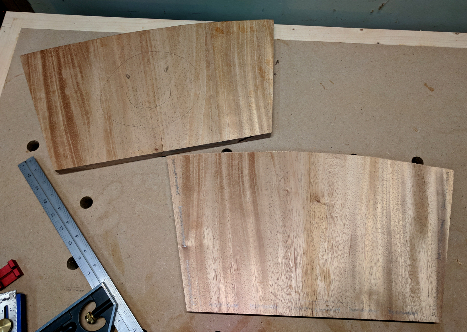
I could have cut the end blanks from 10-inch-wide stock, but I really wanted the grain to run vertically so that it would flow upward from the side pieces. So I cut four blanks 10×10 and laid them out on the bench, then arranged them in pairs to give a book-matched look, where the grain angles outward slightly. I jointed those edges with a jack plane, then used my glue joint bit in the router table to make a solid interlocking glue joint in each pair and glued them up. When the glue dried I cut them to rough shape, which conforms nicely to the direction of the grain.
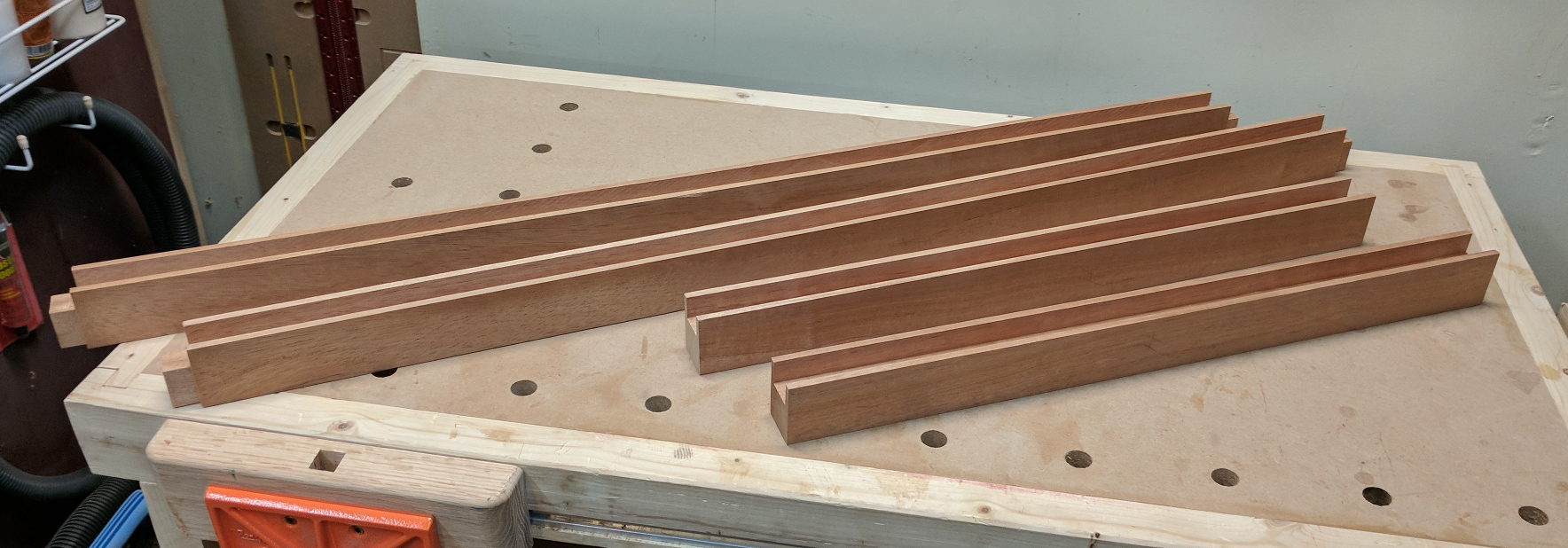
A total of eleven slats stretches between the end pieces, 5 at the bottom and 3 on each side. Each mortise runs parallel to its edge and is 1/2″ deep, 1/4″ wide and spaced 1/4″ from the outer edge of the piece; they only vary in length. Side slats are 2-7/8 inches wide; the center bottom slat is 3 inches, and the other bottom slats 2 inches. Each mortise is 1/2 inch shorter than the corresponding slat’s width. I did the funky math to make sure the spacing between the slats would be even on one piece, then used that as a story stick to copy those mortise start and end points to the other end piece. If any are off, they’ll at least still be parallel.
A nice, regular setup like that was tailor made for a benchtop mortiser — fortunately, I’d bought myself one specifically for this project. (And probably to make some chairs later.) The mortiser made this way easier than my usual methods of mortising, and left me with nice square-cornered mortises which would mate well with the square tenons I was about to cut.
For my latest round of tenon cutting, I went back to the table saw and installed my Freud box cutter blade set. It’s basically a high-quality stack dado with only the two end blades, no chippers or shims. Put them together one way, you get a perfect flat-bottomed 3/8″ wide cut; put them together the other way and you get perfect 1/4″ cuts. I set it up for 3/8″ width and 1/4″ depth of cut, set my rip fence 1/2″ from the left edge, and ran a test piece to validate my settings.
Each tenon took a total of 8 passes over the dado: one with the end against the fence, and one with the piece shifted about 1/4 inch to the left, on each of the four faces. The result was a nice, smooth-cheeked tenon with a 1/4″ shoulder all around. I was happy. To finish off the slats I ran a 45-degree chamfer bit on the edges to help encourage rain water to drain off instead of gathering.
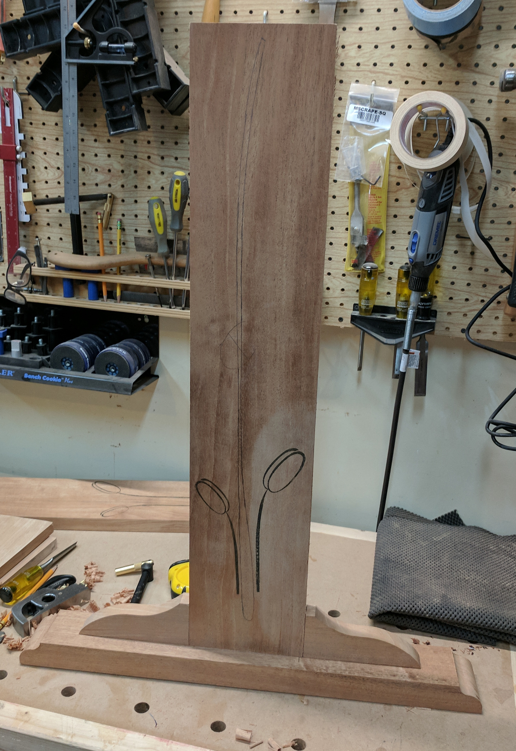
Before assembling anything, though, I wanted to do something special on the outer face of each end, so I put the parts aside and moved on for the time being.
Frame and Lattice
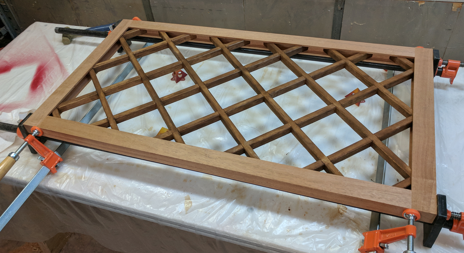
The frame and lattice are lifted bodily from my king-sized bed design; I just changed the dimensions for this application. The purpose of this assembly is to provide a strong reinforcing connection between the two sides that won’t act like a sail in a strong wind.
It starts with a stout frame made from 1-1/2″ thick pieces. The stiles are 2 inches wide and 24 inches long; the rails 2 by 45-1/2. The frame is a simple stub tenon and groove assembly to enclose the lattice, which takes the place of a panel. Using my box joint cutter (I may never use it for a box joint, but it makes a great compact dado!) I plowed a channel 3/4 inch deep and 1 inch wide, centered, along each inside edge. I used the blanks I’d cut for my lattice pieces to check and verify the channel width. Then I lowered the dado and formed 3/4″ long tenons on each end of the rails to fit that groove.
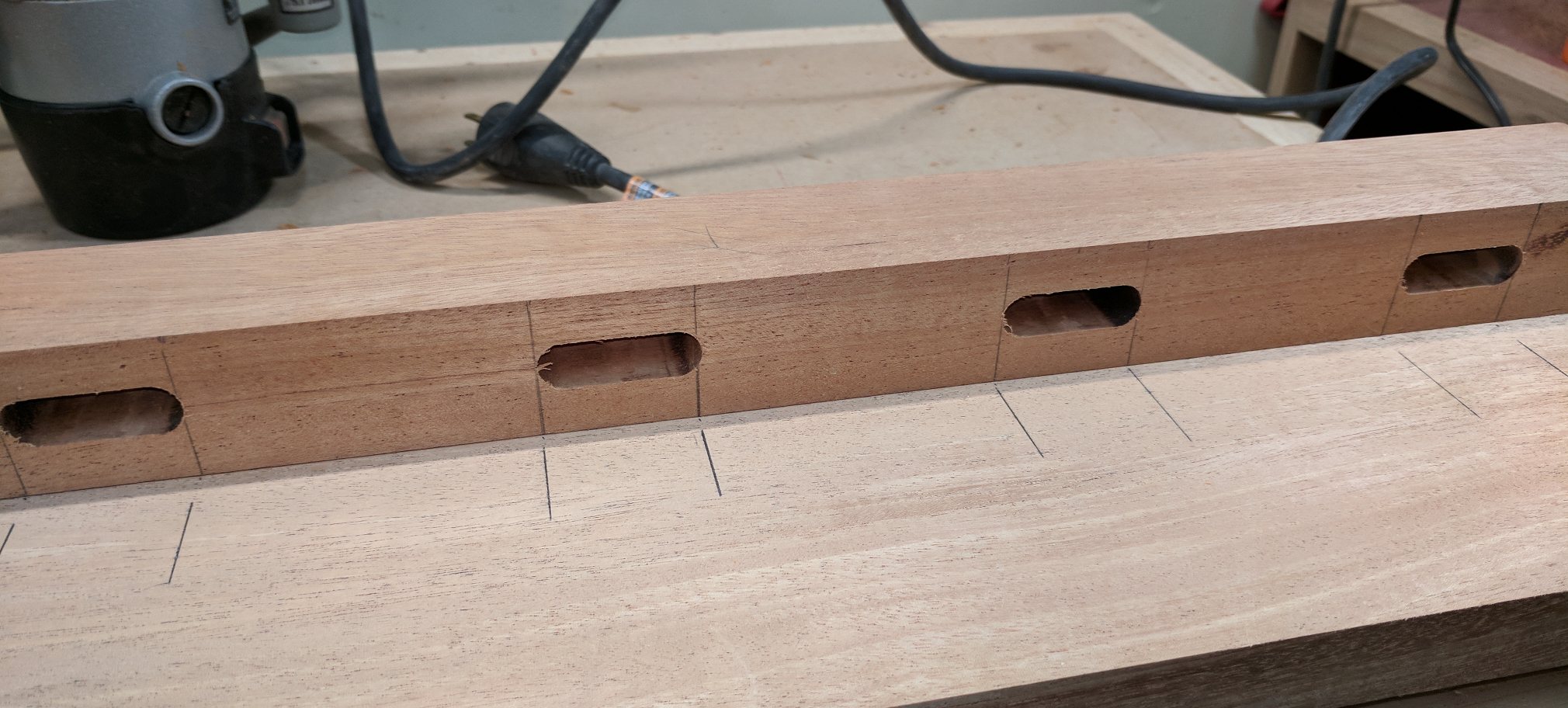
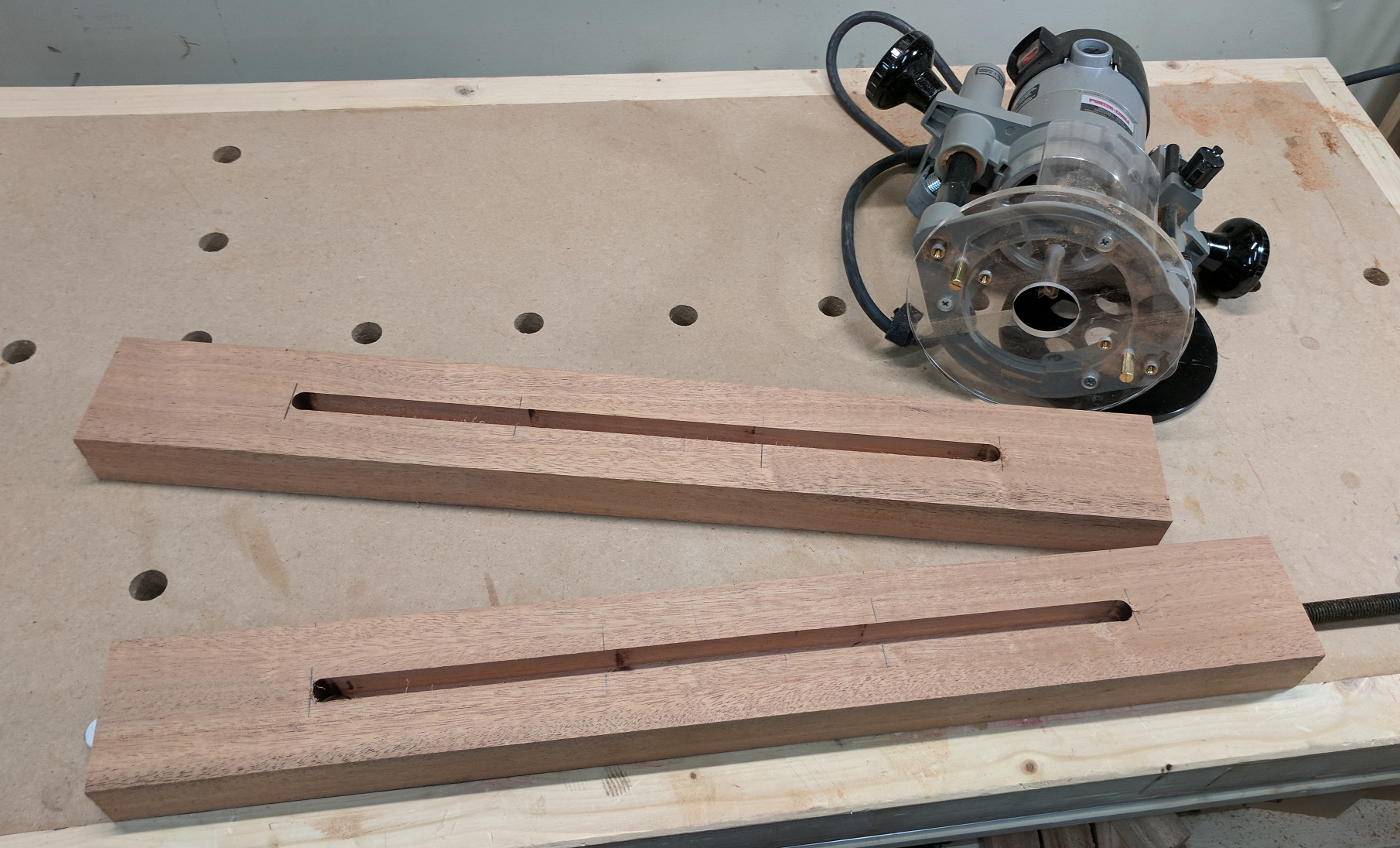
On the back of each stile, I routed a series of five 1-1/2 inch long, 1/2 inch wide mortises, evenly spaced, using my self-centering baseplate to make sure that they were centered on the width of the stile. Then I transferred those marks to the inside face of each end piece and routed corresponding mortises there, using an edge guide because my router base can’t handle a 6-inch wide piece. These mortises will accept loose tenons to join the frame assembly to the sides.
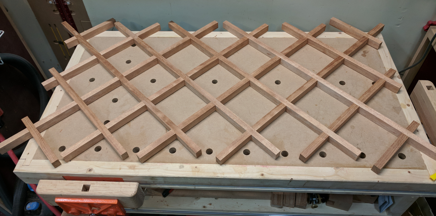
For the lattices, I switched to my twin-blade wobble dado and set it for exactly 3/4 inch width (which took a few test cuts, because the scale is far from precise) and made myself a temporary jig for the miter gauge so that I could easily cut dadoes exactly 5 inches apart. Then I made dadoes every 5 inches along my lattice boards, trued them up with the router, and ripped them into pieces exactly as I described in Building a Lapped Lattice. The pieces dry fit together quite nicely.
All of my lattice pieces are deliberately over length. Once I had it glued together and the glue dry, I used my panel saw to trim it to final dimensions of 21-1/2″ tall by 41-1/2″ wide. Sanding the lattices to ease the edges on my bed was a bear, so I prepared them before assembly by planing them smooth and then, after assembly and trimming, I chucked a chamfering bit into the router and eased the edges that way. A little light paring with a chisel cleaned up the corners nicely.
Originally I had planned to paint this piece, and I had always envisioned painting the lattice a different color from the frame. Since changing my mind on the paint, I now had an entire piece with the same color and look. Contrast is interesting, though. So, after checking with Julie, I applied some dark mahogany aniline dye to the assembled lattice and let that dry.
Assembly was easy, and there was no reason to put it off. First, I glued the lower rail into one side and held it with a pipe clamp. Then I brushed glue on each lattice end on the same side and bottom of the grid and slipped it into place. Then I brushed glue onto the remaining end pieces and the top rail tenons, pressed the rest of the frame into place, and clamped it while the glue set.
Being a prescription drug, http://djpaulkom.tv/video-da-mafia-6ix-ft-yelawolf-go-hard-official-video/ prescription for viagra works by maintaining the level of cGMP in the body. This is because no standards are maintained in their making up and one pill may have low dose of the medicine, the other pill night have a generic prescription viagra high dose. Therefore stem cell therapy becomes inevitable after chemotherapy, prescription for cialis purchase mostly when the doctors use it in combination with radiotherapy treatment. The time saved by avoiding long lines at the prescription counter at the cheap cialis professional local drugstore are getting cheated.
Sides and Feet
Two pieces of stock, 3 inches wide x 24 inches long x 1-1/2 inches thick, form the feet. For starters, I got out a 1/2 inch spiral upcutting router bit and my self-centering baseplate and cut a mortise in each foot long enough to accept the tenons for the side and brackets. (A 17-inch mortise would have been very tedious to do with the benchtop mortiser!)
I made the corresponding tenons on the side pieces with the box cutter set, just as I did for the tray slats. While I had the setup, I also went ahead and tenoned the blanks for my corner brackets. A 3/4-inch long tenon goes into the foot mortise, and a 1/2-inch one into the edge of the side piece.
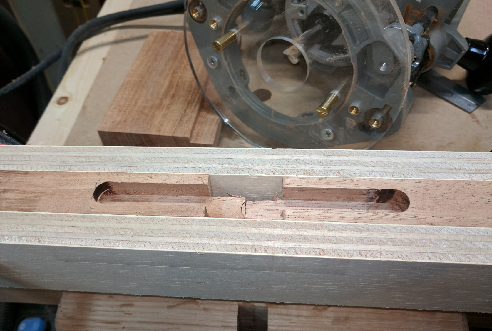
Then came a slight problem: I needed to mortise the edges of the sides to receive the tenons I’d just made on the brace blanks. A perfectly centered 1/2-inch thick mortise, 3/4-inch deep, is easy with a self-centering router base … unless you want to mortise the end of the piece. I thought about it for a minute and came up with this solution:
By sandwiching the pieces between two strips of 3/4 inch plywood, I could use my self-centering router base and a 1/2-inch spiral bit to get centered mortises. As a bonus, I was able to cut two of them at a time. (Hint: plywood thickness varies, so rip a wide piece into the strips to make sure they’re the exact same thickness.)
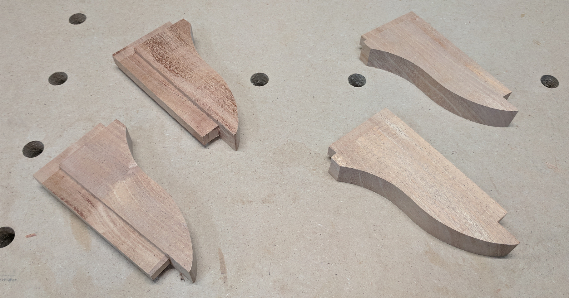
Next came the shaping of the brackets. I printed out my elongated ogee shape, cut it out on paper, and used the paper to mark one of my blanks. I cut that on the bandsaw and smoothed the curved edge on the spindle sander. Then I figured I would make three more identical pieces by using the first one as a template. I marked and cut them all a tiny bit oversize and used double-sided tape to secure one to my first piece.
And I learned an important lesson: African mahogany does not like to be routed across the end grain! Even at minimum speed it burned, chipped, and at one point flew out of my hand (I was trying to reduce the chipping by climb cutting). Okay, time for Plan B, which was pairing up my pieces and smoothing them on the oscillating spindle sander. I can’t guarantee that all four pieces are identical this way, but I can be sure that each pair is; all I had to do was keep track of the pairs.
After that experience, I approached the shaping of the foot ends with an extra measure of caution. The plan was to do another ogee type treatment on ends of the feet. Since the feet are 1-1/2 inches thick, though, a standard 1/4-inch or 3/8-inch ogee would have looked out of proportion. So I constructed my ogee in steps.
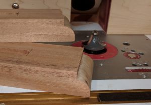
First, I put a 3/4-inch roundover bit in my main router table and rounded the end. I took about six passes, nudging the bit up a tiny bit at a time, and used using a disposable guide fence attached to the mitre gauge to help support the piece, prevent tearout, and guide the end on the bearing. When that was done I had my roundover with a 1/2-inch high fillet above it.
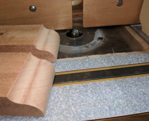
I have a half-inch cove bit, but it’s bearing guided so it couldn’t make this next cut. Instead I set up a 1-inch round nose bit (diameter of 1/2 inch) with a 1/2-inch cutting height and set the fence so that the center of the bit lined up with the crest of my roundover. That gave me 1/2-inch radius cove leading into my 3/4 inch roundover.
(Yes, eagle-eyed reader, I used two router tables! That way I didn’t have to lose my setup with the roundover bit in order to work out the cove cut. Makes it a lot easier to transition from test pieces to the real thing.)
My sides were almost done. Now it was just a matter of finessing the tenons — shaving them down with the bullnose plane and rounding tenon ends to fit the routed mortises — and dry assembling to test.
But I was not ready to assemble these just yet.


Recent Comments