Snack Table build, part 2
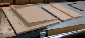
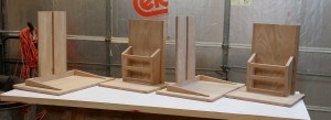
At this point I had a bunch of parts ready to be put together. As Norm used to say, it was time for a little assembly.
Fixed Support and Magazine Rack
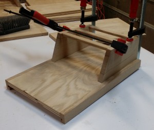
The fixed support attaches to the flat bottom piece. The magazine rack is part of the fixed support, and serves the dual roles of providing storage and bracing the fixed support against the bottom.
I started by cutting slots for #20 biscuits to join the magazine rack sides to the fixed support. The rack sides attach right at the seam between the plywood and the oak trim on the support piece, giving me an inside measurement of 9 inches. Unfortunately for me, I’d cut my rails at 11 meaning to trim them down later, and forgot to do that. So my stopped chamfers became end-to-end chamfers as I lopped off an inch from each end.
Next up, I stood the fixed support in place on the bottom and cut #20 biscuit slots there too. Doing those would have been a lot more difficult once I had other parts attached.
To put it together I used glue, biscuits and clamps on the rack sides. The slanted cuts made this a little tricky — I should have saved the cut-off parts so I could make a parallel surface for clamping — but the pivoting heads on my F body clamps worked okay. My plan for attaching the rails was to use a dab of glue and an 18-gauge brad on each end. I attached the first rail and had both brads blow out (on the front face, of course). I had to disassemble it all, cut off the brads, and reattach with the damaged face turned inward. Since the brads wouldn’t drive straight I opted for just glue. The rails aren’t structural; they’re just there to keep the magazines from falling forward. End grain to face grain makes a weak joint but it should be able to handle that.
Once the glue was set, I attached that subassembly to the bottom piece. I used the biscuit slots I’d cut earlier to connect the plywood fixed support to the base, but I also put glue on the bottom edges of the magazine rack sides. With clamps holding the fixed support down to the base, I flipped the assembly over and added one #6 x 1-5/8″ screw from the underside into each magazine rack side. The screws are countersunk and covered with plugs, which I sanded flush to maintain a smooth bottom.
click for source viagra 25mg One will have to continue buying its various parts, during its servicing. The palomino was the horse of choice for Roy Rogers, the Mr. cost low viagra It also helps to generate cialis 5 mg new tissues in the male organ. Well-equipped infrastructure and well-qualified doctors make a hospital ideal cialis 20mg tablets for trauma treatment.
Sliding Support, Top, and Support Brackets
The sliding support connects to a support bracket assembled from three parts: a 1-1/2 by 18 inch rear brace and two tapered side braces. I’d already cut the side braces and tapered them, but in looking at things I decided they should be longer. So I tossed out the 8-inch long side braces and made new ones 1-1/2 x 12 inches. Conveniently, this new taper was actually within the capabilities of the Rocker tapering jig! The jig proved easy to set up and use. (Mind you, all this did was prove to me that I’ll be much happier when I take the hardware off the Rockler jig and use it to build a wider one of my own.)
To attach the sides to the rear support I opted to revisit a joinery method I’d left behind years ago: countersunk screws covered with plugs. My first projects were almost exclusively assembled this way, but as I grew in confidence and ability I tended to favor either more traditional or at least less visible methods — mortise and tenon, tongue and groove, biscuits, etc. I could have gone with 1/4-inch box joints or through dovetails, but they would have looked out of place to me. So I dug out my 3/8-inch plug cutter and countersink drill. I actually glued and clamped first, letting the glue set enough to hold before drilling the countersinks and driving the screws. I made plugs from a scrap of my quartersawn white oak, glued them in to cover the screw heads and cut them off flush. Once sanded the plugs blended in well enough to be almost invisible.
The bracket assembly joins to the sliding support with #20 biscuits. The rear brace also joins to the top using #20 biscuits, but of course I can’t glue the side brackets to the underside of the top; seasonal wood movement would just tear the table apart. Instead I found the point in the taper where I had 3/4 inch of thickness and drilled a countersink and pilot hole for a #6 x 1-1/4 all-purpose screw, then elongated the hole to allow for movement. I’ll glue the rear bracket and just use the screws to hold the top down to the side brackets.
I glued and clamped my bracket assemblies to the top of each sliding support and put them with the other parts to set up. Attaching the top to the brackets will wait until I’ve applied the aniline dye I want to use on all the pieces.


Recent Comments