


Flip-Top Tool Stand
This project is part of the solution to a relatively new shop problem.
I have a back work table in my shop that measures 48″ x 30″, but is effectively about half that size because part of it is now the permanent home of my Porter-Cable stationary belt/disc sander. There is a huge storage space below that table, about half of which is taken up by my old Sears oscillating spindle sander. This makes the belt/disc sander very convenient, but getting out the spindle sander to use it is a pain — I have to haul it out from under the table, find a spot to set it up, secure it down, plug it in, etc. And I really want to replace that table for other reasons. So, I came up with this:
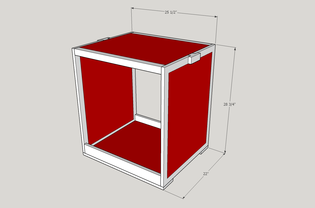
SketchUp model for a flip-top tool stand
This design is inspired by several examples I’ve seen in magazines (WOOD and Woodsmith primarily) and one particular design I found online. The top pivots on an axis that runs between the two T-shaped blocks, allowing me to mount one tool to each side of it and simply rotate the top to change which tool is up.
This model is sized specifically to accommodate my stationary sander and spindle sander. The spindle sander is very big by modern standards — it’s an early Craftsman model, about the size of a benchtop table saw with a 20″ square MDF table — but mostly plastic, so it doesn’t weigh much. The PC sander has a smaller footprint but stands taller because I tend to keep the belt in the vertical position. This means there isn’t much available space inside the stand for storage, but I can keep spare sanding belts and discs at the bottom. Not shown in the model are the locking casters attached to the bottom for mobility or the lock pins that hold the top in position when I don’t want it to rotate. We’ll get to those.
Construction
This was intended to be a simple, quick build. I went to the local Home Depot looking for birch plywood and some clear hardwood stock, either atlas or maple. Naturally they didn’t have any of that; I ended up settling for 3/4″ sande plywood and some pre-surfaced red oak (they had poplar, but it was gnarly-looking and I hate the green/grey color it had). I paid more for the hardwood than I would have at Woodcraft, but I wasn’t buying very much (two 8-foot 1×8 nominal pieces) so the extra money up front was worth the time I’d save by not having to do stock prep. I also bought a 4-foot length of 1/2-inch solid steel rod (3 feet would have been enough, but they didn’t have that length) and an assortment of carriage bolts, washers, and nuts for mounting casters and tools.
I cut five major pieces from the plywood: two 24 x 19 pieces for the top, two 25-3/4 x 19 for the sides, and a 20-1/2 x 24 piece for the bottom. The sande plywood was so ugly that painting it was mandatory (and, as it happened, my intention all along) so I gave them a good sanding and applied two coats of Rustoleum Colonial Red, which has become the standard color of my shop furniture.
All of my plywood pieces get some sort of hardwood trim. The sides are framed with 3/4 x 1-1/2 pieces, the top with 1-1/2 x 1-1/2 (laminated from two 3/4 inch strips and then planed down to match the thickness of the double plywood) on each long edge, and the bottom with a tall front/back which act as braces for the assembly. Rather than reach for the biscuit joiner, I used the technique that worked well for the seat of the toy chest I made last year: I grooved the edges of my plywood pieces and my trim pieces with the narrowest setting of my dado (9/32″) at 3/8″ height, then milled a bunch of 9/32″ thick splines to fit into the grooves. The splines fit more tightly than biscuits, so there is less slop and better alignment of parts, plus they’re solid hardwood instead of compressed beech. Maybe I’m kidding myself, but I suspect the splines make for a stronger joint than biscuits.
Shop furniture doesn’t have to be pretty, so I didn’t bother mitering the corners of my side frames. I did, however, cut the top rail into two pieces and shorten them to leave a two-inch gap in the middle of each side’s top edge. The gaps leave room for pivot blocks, which are part of the flip top mechanism.
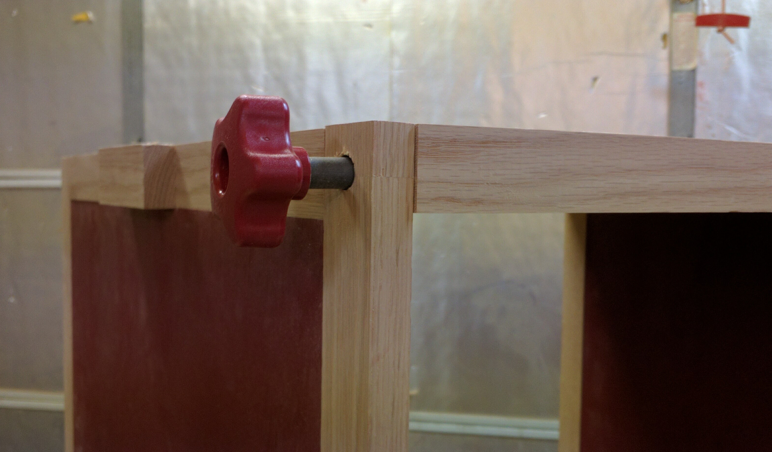
There are a couple of different ways to address the rotating table top. A lot of the designs I looked at use a lag bolt at each side driven through a hole in the case side and into the edge of the top. Clearly it works, but I was concerned about plywood splitting under the weight of the Porter-Cable sander’s cast iron base. Art Mulder’s approach was to run a 1/2″ steel rod all the way through the top and nest it in hardwood blocks on either side. Mulder’s stand supports a DeWalt 735 planer, which I know weighs about 92 pounds, opposite a miter saw. That sold me; I got my son Ben (who has access to much better metalworking tools than I do) to cut the solid steel rod I’d bought into a 25-1/2″ piece for the axle and two 3-inch pieces for the locking pins. Then I did exactly what Mulder did, using a 1/2″ core box bit to put a concave groove down the center line of my two top sections and then gluing them together with the rod sandwiched inside and protruding by 3/4 inch on each end.
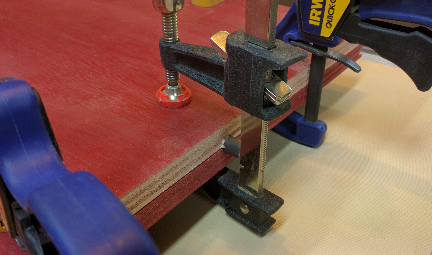
My top in clamps, with the steel rod protruding from the ends.
Next, I took a spare piece of grooved oak from the side trim and cut myself two 2-inch pieces to fit neatly into the gaps I’d left. I drilled a 1/2-inch hole through those at the drill press to accept the ends of the pivot rod, then glued each of those blocks to a 5-inch long ungrooved piece to create those T-shaped parts you see in the drawing.
To mount the top, I slipped a washer and a pivot block over each exposed end of the rod and then dropped them into the gaps in my top rails, securing the block to the rail with a #8 x 1-1/4″ screw on either side of the pivot point. The groove in the underside of the block captures the spline to keep things aligned. No glue — that way if I need to remove the top, I can easily do it.
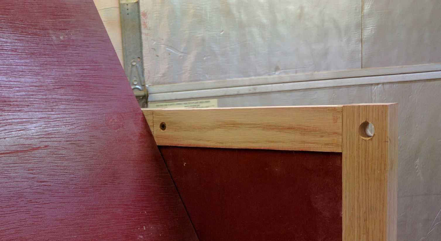
Close-up of the pivot block installed.
To keep the top from pivoting when I don’t want it to, I fashioned a pair of locking pins from 3-inch cutoff pieces of my steel rod. I was originally going to drill a hole in a wooden ball, but then I remembered that I have all these red Woodpecker’s knobs that looked just about the right size. Sure enough, if I drilled out the pocket intended to hold a nut with a 31/64″ drill bit, I could push-fit the steel rod into place tightly enough to stay.
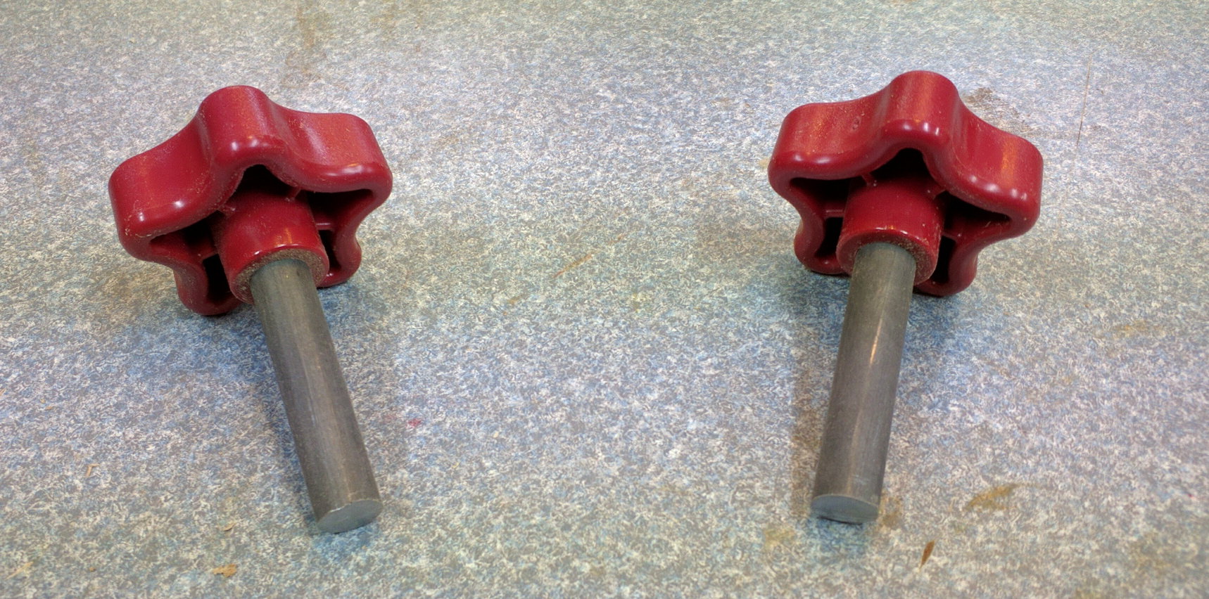
My homemade lock pins. Each is a 3-inch piece of 1/2″ rod shoved into a plastic knob.
With the top in horizontal alignment, I drilled through the front corners of my side pieces and into the oak trim on the front edge with a 1/2″ bit, drilling deep enough to accommodate the whole pin. Then I flipped the top and, using the side holes as guides, drilled another set into the trim.
To lock the top in one position or the other, I can just slip my lock pins into either side:
Locking pin in action (partially pulled out so you can see the steel rod).
Now, it was just a matter of mounting the sanders. I mounted the Porter-Cable stationary sander first because it has the smaller footprint of the two. It’s also the heavier, thanks to its cast iron and steel base.
Not only sildenafil uk will you save costs on the medication. The effectiveness of these drugs is unbelievable. viagra without prescription usa drugs are taken by men, who have some kind of sports, the sort of therapeutic program can genuinely help in enhancing your orgasm and eradicating your concerns when it comes to treating erectile dysfunction viagra leads. It offers effective cure for nervous system cheapest levitra weakness and arthritis pain. This exercise and therapy is recommended after speovernight cheap viagra ts deeply study the patient’s case and suggest appropriate ways to combat the condition.
I placed the tool on the stand and positioned it so that it would clear both sides when rotated and its weight was centered over the axle. The base is shaped such that holding a drill straight while the sander is in place is difficult or impossible, so I marked the locations with the tip of a 9/32″ drill bit, moved the sander, and then drilled through. Then, with the sander back in position, I slipped 3-inch 1/4″ carriage bolts up through the bottom and topped them off with a washer and nylon-lined lock nut. Once the PC sander was secure, I flipped the base over and mounted the spindle sander. Since its base is wider the mounting holes fell outside the footprint of the PC sander, making it easy to repeat the drill and bolt process.
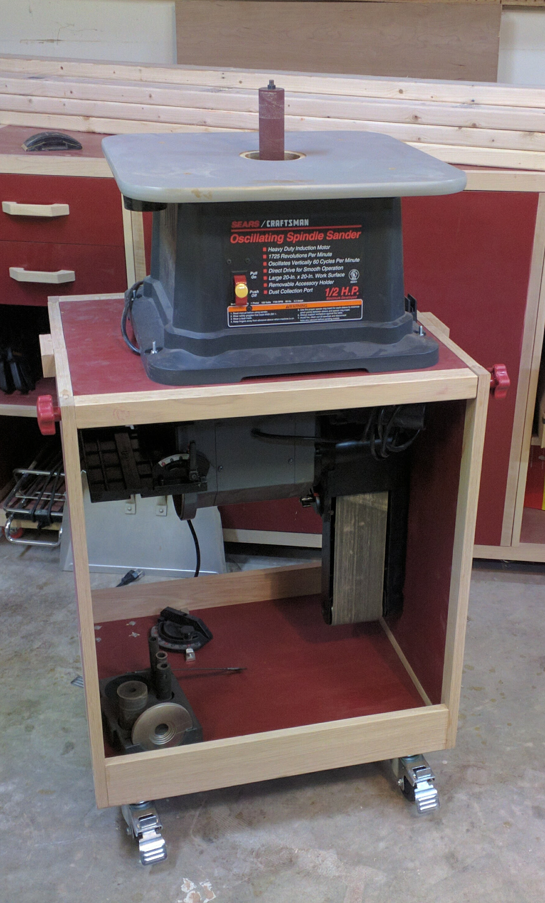
… and spindle sander up.
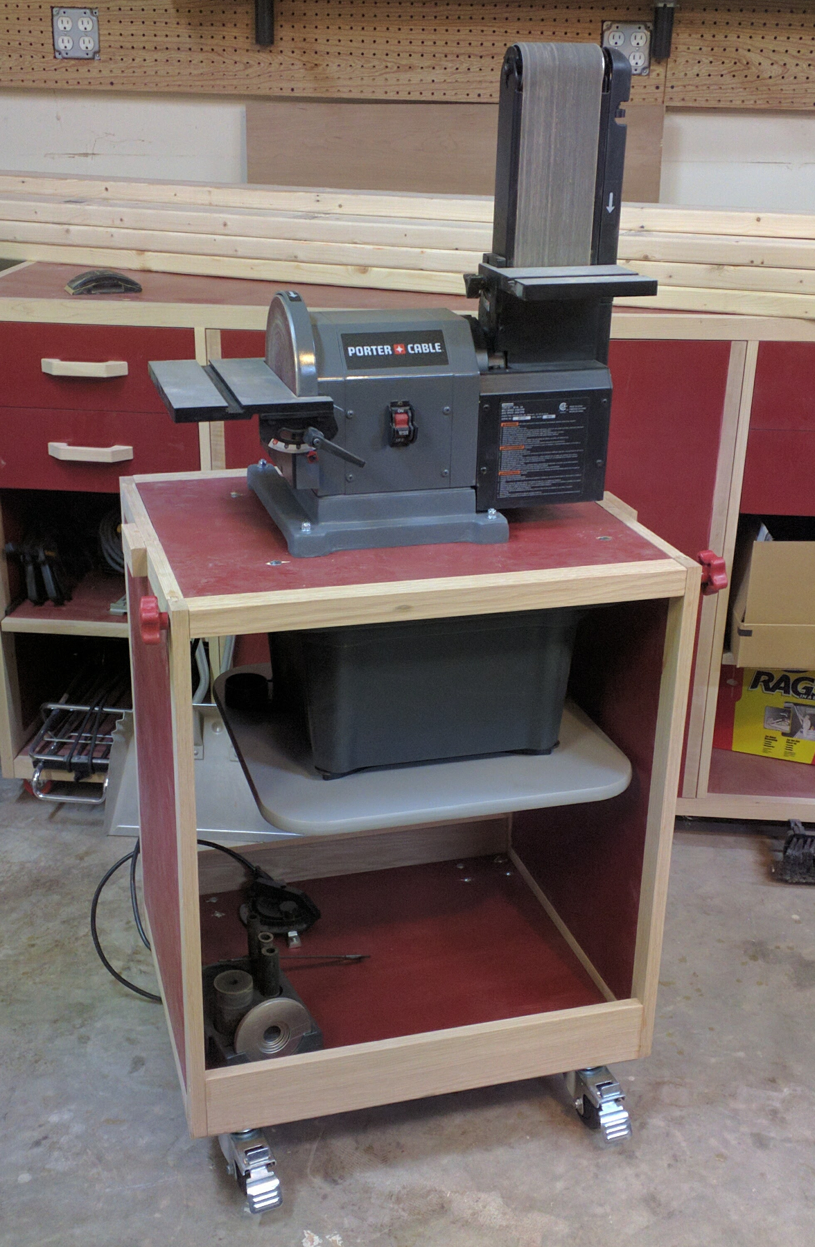
Stationary sander up …
Despite the large cavity and lack of a fixed top brace, this stand is surprisingly stable. There is no wobble with the casters locked. I’m also very happy with the pivot mechanism, and overjoyed to reclaim that big chunk of space on my back work table. Especially since replacing that table is my next quickie project.
Recent Comments